coax trap calculator
This page is intended to help design Coaxial Cable Antenna Traps for a multi-band trap antenna. The first part is just a short introduction into trap antennas. Next is a section that provides dimensions and material specifications for a set of Coaxial Cable Traps. Following that is a section that allows the user to create a custom trap using their specified frequency, coax, and coil form. That can be useful when the user wants to change the trap frequency, use a different coaxial cable, or has different coil form material than what is specified in the second section. The program behind the web page then calculates the necessary physical dimensions to realize the trap.
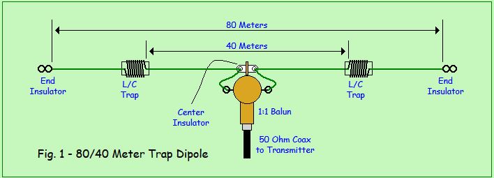
The Multi-Band Trap Antenna
A trap antenna uses L/C parallel tuned circuits to provide multi-band dipole antenna that effectively switches between bands automatically. The input impedance on each of the design bands will be such that a tuner will not be needed when going from one band to another.
A trap dipole, in it's simplest form, might be a two band antenna for say, 80/40 Meters, as in Fig. 1. The total length of the 40 Meter section of the antenna is calculated by the usual formula, listed on the left and right. These simplified equations are based on the standard wavelength formula of λ(m) = 299,792,458/Frequency (Hz) and accounts for a Velocity Factor of 0.95. For 7.1 MHz that would be approximately 66 feet or 33 feet for each side of the Balun. The trap, which is tuned to 7.1 MHz, will present a high impedance and effectively isolates the 40 Meter section of wire from the extended 80 Meter wire. Leaving you with a standard 40 Meter dipole.