Make a Vertical Bazooka
Vertical Bazooka
An article by VE3VDC LD Blake
Build a Vertical Bazooka, which is made entirely from coaxial cable.
The antenna itself is an off-center fed vertical dipole made by flipping an electrical quarter wavelength of braid back over the outside of the coax. The center lead of the coax forms one half of the dipole and the braid forms the other. The resulting antenna has a low radiation pattern and an impedance of 55 - 60 ohms.
One of the more interesting features is the braid itself. By folding an electrical quarter wavelength of braid back over the insulated coax we are forming both a dipole and a "bazooka" (sleeve) balun, a coaxial 1:1 balun that greatly reduces feedline radiation. The braid side of the dipole ends up considerably shorter than the top element because of the interaction between the braid and the coax. The outer braid couples with the inner braid to form the balun and is thus affected by the velocity factor of the coax.
You can use the formulae in the diagram above to create Vertical Bazooka dipoles for any frequency. But please notice the formulas shown will deliberately start you off with the top section too long, so you will have to trim it for the best SWR.
You can build a mobile "emergency" version of the Vertical Bazooka by attaching a length of non-conductive cord (nylon line) to the top of the antenna. With a weight on the free end of your cord, you can simply toss it over any nearby support and hoist the antenna up into the air for use.
If you like you can also build a self-supporting version by sliding the finished antenna into a length of "Schedule 40" PVC plumbing pipe.
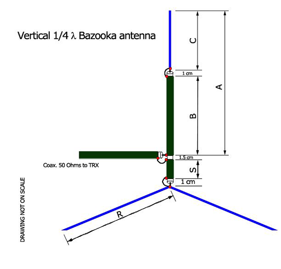
The design formulas are quite simple :
Dimensions in feet
Dimensions in meters
The angle of the radials will be idealy between 35° and 45°
Vf (velocoty factor of used coax) depends of the type of cable. Don't trust to much the clasic 0.66 value : the best is to mesure the Vf with a antenna analyser, results are some surprising (espacialy when you use old coax cables).
Applied as there are, those formulas gived me results close to what theoreticaly expected.
Tuning The Vertical Bazooka
The Vertical Bazooka is easily tuned by clipping short sections from the end of the exposed center conductor of the antenna.
There are, however, some precautions you must observe. This is a dipole, which means it has easily disturbed high impedance nodes at both the tip of the top section and the bottom of the braid. It is an absolute necessity that you get the antenna out into a clear area for tuning. If at all possible, you want at least 1/2 wavelength of clear space all around the antenna. More is better.
Probably the best strategy is to tape the antenna to the side of a length of white PVC tubing so that you can stand it up during tests and tilt it over to clip the top section. Alternatively you can temporarily attach a non-conductive cord and hoist the antenna up and down from a tree branch or clothesline, being careful of the clearance requirements.
Also please note, these clearance requirements include you as your body capacitance can upset the readings. If you're building an emergency version it's no problem as you can simply play out the feedline and work from the other end. If you're working on a self-supporting version you will need to add a length of feedline to enable you to get back from it during tests.
Once you have the antenna in a testing position, take SWR readings at the top and the bottom of the band you've cut the antenna for. Your first readings will (hopefully) be terrible, with the bottom of the band reading a little bit better than the top. This will tell you the antenna is too long... so you're set to begin trimming.
With the formulas used it is very unlikely the antenna will start out too short.
You should note that you will not likely get a "flat match" or 1:1 SWR from this antenna. It's feedpoint impedance varies from 55 to 60 ohms, so you should be happy with anything under 1.5:1.
Assuming the antenna starts out too long:
- Clip a few millimetres from the free end of the top section.
- Repeat your band edge measurements.
- If the low end of the band is still better than the high end, go to step 1.
- If the low end and high end readings are equal, you are done.
As you are clipping, the SWR at the low end of the band may come down then start to move back up. That's ok, it's just the antenna's resonant frequency passing the low end of the band. Once you complete the clip and test cycle the resonant frequency should be near center band and you should have an SWR curve that has equal readings at both band ends and a somewhat lower reading in the center.